Wet Exhaust System
Issues
By Cameron Sharpe — Seastar, 32-128,
Port Ludlow, WA
and Jim West — Kotuku, 32-197, Blaine, WA
Summary: This report
covers the investigation and potential solutions for
wet exhaust system leaks on Nordic Tugs manufactured
in the 1998 to 2002 time period. Due to continuous
product improvement by Nordic Tugs, the following may
apply only to the specific boats of the vintage covered
by the report.
From time to time, we've
read of the fiberglass reinforced pipe (FRP) in wet exhaust
systems cracking or leaking. When
we purchased our 1999 model Nordic Tug, Seastar (NT32-128
with a 220 HP Cummins 6BT5.9M), in December 2005, the
survey indicated seepage from the FRP section of the
wet exhaust system under the settee, just aft of the
90-degree elbow exiting the engine room.
In January 06, the shipyard wrapped
fiberglass mat around the leaking FRP section, halting
the seepage. Although
cracked and leaking FRP is often blamed on
over-tightening of the T-bolt connecting clamps, ours
was chemically bonded with no clamps. We soon discovered
another prominent failure cause.
At
the '07 Nordic Tug Rendezvous at Roach Harbor,
WA, Joe Franett, VP of Operations at Nordic Tug, came
aboard the Seastar to look over the area that had been
seeping. As we peeled back the insulation, we discovered
the fiberglass wrap was charred and the FRP was seeping
again. Joe suspected we were getting excessive
heating from engine exhaust gas, and suggested we gather
actual temperature data on the FRP. Joe advised
that 110° F was the target operating temperature
for FRP. He also advised us to review the exhaust
inspection and maintenance steps suggested in
the Tech Tips of Nordic Tug's newsletter "Waypoints
#11."
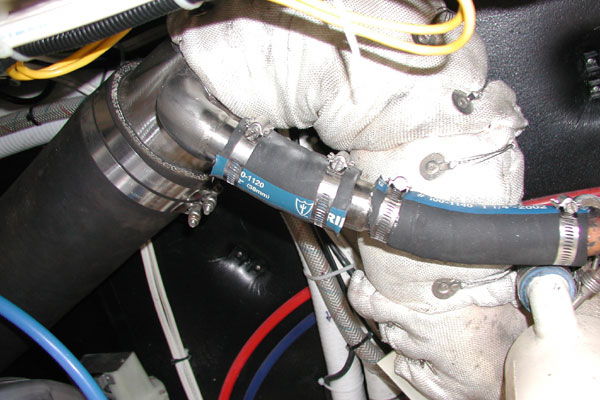 |
NME
wet exhaust water injection elbow showing
additional 18" lift. (Click to Enlarge Photo) |
Soon I was in contact with Jim
West and several other tuggers who had the same or
somewhat similar issues. Jim
and I (working on our respective boats) spent most of
the summer of '07 consulting with Cummins, Nordic,
National Marine Exhaust, Unicraft Marine Products (mufflers
and FRP) and Sherwood Pumps to gather technical and engineering
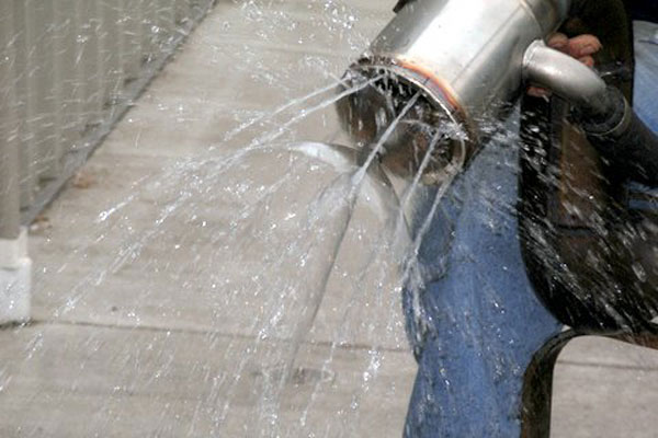
data. We also conducted many flow tests, spray
tests and sea trials to document what actually was happening. A
number of other tuggers contributed technical information,
shared their experiences and helped us locate resources.
First,
a short description of the typical wet exhaust system.
An engine-driven pump (1:1 ratio on the Cummins) passes
seawater through the transmission oil cooler, then
the engine heat exchanger and finally injects the water
into the hot exhaust gas from the turbocharger. The
water cools the exhaust gas from the 350-800° F
range to a much lower temperature that can be handled
by the FRP used in the exhaust system downstream. In
many cases, a water lift muffler is mounted
adjacent to the engine, achieving the same objective,
but taking up valuable engine room space. Briefly,
here's what we found.
-
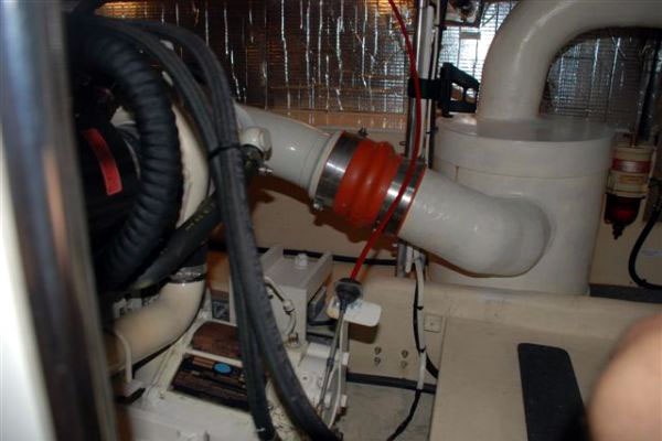 |
Water
lift muffler typical of Nordic Tugs 42
(Click
to Enlarge Photo) |
Cracking and leaking of the
FRP wet exhaust pipe appears to be caused by hot
exhaust gas overheating the FRP (we measured operating
temperatures on the FRP from 245° F to 275° F). The
water injection elbow, with a proper hole-pattern
and adequate water flow, should quickly cool the
exhaust gas down to an operating range of around
110°
F. Depending on
the manufacturer and specific materials used, we have
been advised that the thin-wall FRP is generally rated
for 125° F continuous and 150° F intermittent.
Some newer types of FRP are rated as high as 200-350°
F continuous. Higher operating temperatures,
like those we measured, appear to bake the resin out
of the older type FRP, causing brittleness and pinhole
leaks.
-
The M71 Sherwood pump (#10615
impeller) used on our 220 HP Cummins 6BT5.9M engines
appears to be marginal for this application. It is
rated at 22 GPM at 2600 rpm, but only about 10 GPM
at 1200, and 11.8 GPM at 1400 RPM. Nordic used
a well-constructed National Marine Exhaust (NME)
wet exhaust elbow in many NT 32s, which rises about
18" higher than the original Cummins setup. This
provides improved surge protection from seawater
backing up into the turbocharger, as well as more
room in the engine compartment. But
it also adds 3/4 lb. additional head to a
marginal raw water supply.
-
The 90-degree elbow directing
the combined gas and water exhaust aft out of the
engine room creates spiral turbulence with hot spots
at the top of the pipe about every 18". The
hot exhaust gasses cool about 10° F each time
they pass the cooler raw water flow in the bottom
of the pipe.
-
 |
Vetus
exhaust gas mixer |
On
Seastar, with a new impeller in a good pump, clean
intake strainer, clean engine heat exchanger, but
with about 10% obstruction in transmission cooler,
we measured 245° F on the top of the FRP just aft
of the engine room. Later, with the entire
system squeaky clean, temperatures dropped to 182°
F which was still way over the desired temp of 110°
F.
-
Adding a Vetus Injection Water
Mixer just aft of the 90 degree elbow leading from
the engine room, and some improvements on the NME
water spray nozzle design cooled NT32-128 Seastar's
hotspot to 105° F at 1200 to 1800 RPM, and no
more than 118° F during an extended run at 2200
RPM with 750° F Turbo outlet temp.
-
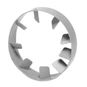
In Jim West's tug
Kotuku, NT32-197, a spiral water discharge nozzle
was added to the wet exhaust elbow itself with impressive
results, but he still has some work left to achieve
the desired temps in the FRP portion of the system.
 |
Spiral
water discharge nozzle on Kotuku
(Click to Enlarge
Photo) |
Conclusions: It
appears that the original design specific to our boats,
with: a) the small Sherwood M71 raw water pump and;
b) the increased height of NME Wet Exhaust elbow and;
c) the water injection spray pattern used at that time
led to inadequate
cooling of the exhaust gas before it entered the FRP
section of the wet exhaust system. The result was overheating
and ultimately leaking of the FRP, often near the T-bolt
clamps. The initial Cummins design appears to be at the
upper limit of the M71 Sherwood pump's capacity
when used with the stock Cummins water injection setup. Adding
the 18" of additional lift with the NME Water Injection
Elbow, results in 3/4" of extra head to the
raw water system. The turbulence issue downstream
of the 90 degree elbow going aft from the engine room
exacerbated the problem. (Current designs are very
good, and are well documented by NT during sea trials.)
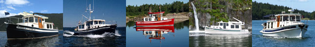
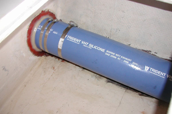 |
Tirdent
VHT high-temp silicone hose on Seastar
(Click
to Enlarge Photo) |
Adding
a Vetus Injection Water Mixer appears to be a simple
and inexpensive solution for the 220HP Cummins application.
(http://www.fisheriessupply.com/online/ Go
to Products, search "Vetus" then to page
8.) Also for the Seastar we substituted Trident
VHT high-temp (350° continuous) silicone hose in
place of the FRP in this area as insurance. (Some other
brands of pipe also now meet this high temperature rating.)
It is also important to configure the water spray nozzles
in the wet exhaust riser to provide a larger number of
smaller streams, concentrating them at the top of the
turbo outlet (hottest exhaust area) to improve heat transfer. For Seastar, we are currently
working on a complete water pump upgrade package to
add the GC5 pump with #15000 impeller. The larger pump adds 33% more capacity
(and opens a host of additional engineering and cost
issues). If you already have the larger pump with
the 15,000 impeller, you probably don't have the
cooling problem. We are also working on a more
extensive report with upgrade part numbers, flow charts,
test data, photos, and discussion of the additional engineering
issues dealing with the pump upgrade. We will post
on this forum when the upgrade package is ready.
For questions for comments, the author
may be contacted at: SharpeC@cox.net
Readers'
Feedback:
Date: January 10, 2008
From: Bob Bevins — NT32-009, Anacortes, WA
After reading the report I have the
following suggestion:
Remove any rise in the exhaust
system and put a vertical loop in the exhaust just
before it discharges
overboard. This keeps a small amount of water
in the exhaust (FRP) section and aids in the cooling. The
loop also prevents water from going into the exhaust
system in a following sea.
My tug has had the loop in the exhaust for the past
twenty years and I have not had any issue with the
FRP getting hot.
|